


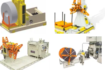

Machine Concepts’ Medium Duty Decoilers are designed to handle coils up to 8,000 pounds per mandrel and coil widths up to 14 inches. These decoilers are typically paired with a Machine Concepts EV/L2 or G2 Precision Straightener.
When paired with a Machine Concepts Straightener, these decoilers can incorporate Hydraulic Self-Centering Adjustment. This optional feature incorporates a hydraulic cylinder with a linear transducer to shift the decoiler to accommodate different coil widths. The coil widths, along with other coil and material specifications, can be pre-programmed and stored in the straightener control memory to adjust the decoiler to different side shift positions based on the material being processed. This is just one of the many features used to make Machine Concepts’ Decoilers operator friendly while providing customers with superior line efficiency.

Standard Features
- Standard sizes for 6,000-8,000 lb Coils
- Manual, Linkage Style Expansion
- Manual Mandrel Rotation with Coil
- Pneumatic Drag Brake – internally mounted
- Manual Turret Rotation (Dual Mandrel Only)
- Pneumatic Shot Pin (Dual Mandrel Only)
- Fixed Lower Base (No Side Shift)
- Manual Clamp Individual Coil Keepers – keeper on each segment. Requires an operator to attach and clamp keepers after a coil is loaded.
Optional Features
- Hydraulic Mandrel Expansion – mandrel segments are expanded and collapsed using a hydraulic cylinder instead of a manual hand crank
- Pneumatic Drag Brake – externally mounted
- Lower Base Traverse – manual adjustment or hydraulic adjustment (self-centering)
- Manual Clamp Ferris Wheel Keeper
- Single Powered Keeper Arm
- Dual Powered Keeper Arms
- Hold Down Arm – non-driven or driven hold down arm mounted to each mandrel (minimum coil widths are required when a hold down arm is purchased)
- Mandrel Rotation Style – hydraulic powered job/mandrel rotation with coil at line speed or electric motor powered payoff
- Coil Guard – guard mounted directly to mandrel head to contain coil clock-spring so strip does not hit personnel walking on back side
- Coil Backstop Guard – guard mounted off of the decoiler (to the floor or common mounting base) to contain coil clock-spring so strip does not hit personnel on back side
- Hydraulic Power Unit – machine mounted or floor mounted
- Coil Reband Arms – incorporates a free standing base with two hold down arms mounted to the floor on the back side of the decoiler. The two hold down arms (one from the top and one from the bottom) will pivot simultaneously to clamp the coil. The purpose of these arms is to provide extra support to prevent clock-spring. This feature is typically used for lines running thick gauge material. When the mandrel job function is engaged, the driven hold down arms will push the strip of material in the direction of mandrel rotation to help thread the material into the straightener.

